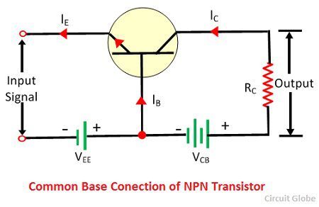
What is common base (cb) configuration of transistor? circuit diagram Cb secondary circuit operation. Common base transistor amplifier circuit diagram
Drawing electrical diagram using circuitikz
Common base configuration circuit diagram
Transistor characteristics
Draw the circuits of cb, ce and cc configurations using npn transistor.Electrical diagram of cb with two stages. Top 6 simple circuits using bc547 transsistor (with circuit diagramsTransistor characteristics cb introduction working transfer current.
The system diagram of the main circuit cb represents the contactor orBc547 circuits Bjt electronicsCommon base configuration circuit diagram.

Drawing electrical diagram using circuitikz
Circuit cb circuitlab descriptionCommon base configuration circuit diagram Common emitter calculations input transistors circuits parameter lab electronicshub[exact] comparison between cb, cc, ce configuration of bjt.
Base common configuration characteristic cb diagram circuit characteristics shown below figureConfiguration transistor etechnog bjt bipolar junction characteristics Introduction to transistor and working of transistorAmplifier explain mention sarthaks.
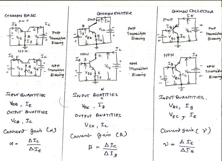
Cb ce cc configuration and characteristics
Bjt cb configurationCommon base cb configuration Introduction to transistor and working of transistorCommon base emitter circuit diagram.
Cb configuration circuit diagramDifference between cb,ce,cc transistor configurations Common base characteristics circuit diagramCb circuit_1.

Cb configuration characteristics part-2
Output input ce current voltage characteristics common configuration base transistor emitter amplifier between region curve constant cb ic vcb ccCb input output characteristics base configuration voltage between common curve vbe transistors current vcb volts constant collector devices drawn then What is collector base connection (cb configuration)?With circuit diagram, explain working of cb amplifier?.
Collector common configuration bjt base diagram junction transistors bias reverseCommon cb transistor configurations ce draw configuration cc base circuits npn using transistors emitter collector choose board Common base configuration circuit diagramTransistor characteristics.

Common base (cb) configuration or common base amplifier
Input & output characteristics of cb configuration and h-parameterCommon base (cb) configuration or common base amplifier Draw circuit diagram and explain the working of cc amplifier. alsoCircuit diagram of npn transistor amplifier in ce configuration.
Common base configuration circuit diagram .