How to use relay with schematic of relay circuit diagram How to use relay with schematic of relay circuit diagram Relay low current circuit switch delay time schematic 12v electronic power circuits control does gr next diagram seekic
electronics repair made easy: Relay found in switch mode power supply
Relay motor control circuit schematic arduino
Arduino high control voltage relays use code relay circuit motor projects output circuits
Dc motor reversing circuitWiring understand Relay wiring diagram and function explainedRelay using motor dc 12v schematic direction change rotation circuit latching switches bistable electrical circuitlab created.
Relay schematic avoid controlling motors damaging used circuitlab created usingRelay circuit motor circuits control forward reverse diagram stop start wiper gr next How to wire a relayMotor dc relay control relays driver diagram bridge motors direction l293d logic module speed pwm controlling microcontroller source info single.

Dc motor control tutorial
Motor dc control remote reversing circuit relay limit diagram reversible switches timer current automatic voltage used circuits ir electronics set[diagram] wiper motor relay diagram ⭐ car main relay wiring diagram ⭐Relay contactor flow thermostat volt newlec relays induction electric.
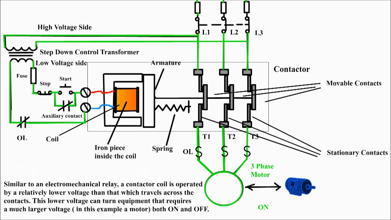
Relay motor diagram wiring starter contactor square electric phase fuse circuit furnas electrical hvac connection magnetic voltage lighting schneider manualPlc application for reduced voltage-start motor control Circuit relay using makingSpotlight wiring diagram 5 pin relay.

Relay circuit diagram switch float example schematic use basic mount horizontal
(a) hardwired relay circuit and (b) wiring diagram of a reduced-voltageRelay circuit schematic basic switch diagram relays use control device connect dot ai hc11 pins port workshop terminals example used 14+ motor control using relay circuit diagramPair of 5v relays.
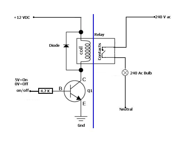
Above is a simple relay control. now, here is what is happening.....Cambiar la dirección de 12v dc motor rotation usando relay Motor control bidirectional relay relays 5v pair diagram singleHow to installation control current relay in three phase circuit.

How to use relays to control high-voltage circuits with an arduino
Relay wiring diagramMotor phase single using relay forward reverse 220v control ac diagram channel there Electrical standards: overload relay working principle and features ofHow to avoid damaging relay used for controlling motors?.
Voltage motor reduced control start plc relay diagram timer wiring circuit electrical application must trapped seconds contacts instantaneous lines alsoRelay relays ncd switching logical Electronics repair made easy: relay found in switch mode power supplyPic controlled relay driver circuit diagram.
Relay 40a spst fused diode rocker prong harness mgispeedware diagrams electric wires lighted
Diagram wiring contactor reverse relay overload circuit forward motor phase power starter direct dol control pdf thermal electrical switch magneticRelay control using simple arduino circuit switch power datasheet lock magnetic turn pc supply parameters 12v 5v plug ac 230v Relay circuit page 11 : automation circuits :: next.grMaking a circuit using a relay.
Relay principleMotor control using relay circuit diagram Relay explanation electrical switchesThree phase motor control circuit. difference between relay and.

V fan relay wiring diagram
Relay control circuit troubleshooting electricalElectrical troubleshooting of a relay control circuit. Relay diagram circuit wiring phase control current three installation[diagram] ac dpdt relay wiring diagram ladder.
Relay driver pic controlled circuit diagram circuits schematic controller ac bridge diode input lineDc motor driver bridge transistor circuit control diagram using circuits relay schematic arduino controlling transistors old Su_chef slices.